

A flared tube end is one of the most reliable ways to make a metal-to-metal seal. Brake lines, refrigerant lines, fuel lines, and hydraulic tubes all depend on it, and a single bad flare can mean a leak, a failed pressure test, or a returned part.
This article explains what tube flaring is, the main flare types and flaring methods, how to flare a tube step by step, and how to recognize and fix the most common tube flaring problems. It closes with what to look for in a tube flaring machine for production.
What Is Tube Flaring?
Tube flaring is a cold forming process that opens the end of a tube outward into a cone at a fixed angle. A matching nut is slid onto the tube before flaring. When the nut is tightened onto a fitting, the inside or outside face of the flare is pressed against the fitting’s seat and forms a metal-to-metal seal, with no gasket or welding needed. Flaring is a core tube end-forming operation, alongside expanding, reducing, and beading.
Flaring vs expanding
Flaring and expanding both enlarge the tube end, but they do different jobs. Flaring only opens the very end of the tube to a set angle so it can seal against a fitting. Expanding enlarges the diameter evenly over a longer length so that another tube can slide inside. Both are the opposite of swaging, which reduces the tube end.
Common flare types
45° SAE flare
The 45° single flare is the standard in refrigeration, air conditioning, plumbing, and many automotive lines. It is usually made on soft copper or aluminum tube and paired with brass flare nuts and fittings.
37° JIC flare
The 37° flare is used in hydraulic systems and is the basis of JIC and AN fittings in industrial, military, and aerospace applications. It is usually made on steel tube and handles higher pressures than a 45° flare. The two angles are not interchangeable, so never pair a 37° flare with a 45° fitting.
Double flare
In a double flare, you first push the tube end into a bubble, then fold it back on itself before forming the cone, so the flare has twice the wall thickness. This makes it stronger and far less likely to crack, which is why it is common on automotive brake lines and other high-pressure, high-vibration lines.
Bubble (ISO) flare
Popular on European vehicles, the bubble flare has a rounded, mushroom-shaped end instead of a cone. It seals against a matching concave seat and is used mainly in brake and fuel lines.
90° flange
When the end is opened to 90°, it becomes a flange. Flanged ends are used with clamps and flat seals, for example in some hydraulic and exhaust connections.
Tube flaring methods
Punch (ram) flaring
A conical punch is pushed axially into the clamped tube end in one or more strokes. It is fast, repeatable, and the most common method on production end-forming machines. Progressive punches can form double flares and deeper shapes in several steps.
Orbital (rotary) flaring
A flaring tool rotates or wobbles around the tube axis as it advances, forming the flare gradually rather than in one push, which reduces the risk of cracking. It is valued for high precision and repeatability and, with well-chosen process parameters, a fine surface finish. Studies have also shown that a rotating punch can lower the axial load and help suppress buckling. Commercial orbital flaring machines typically cover 37°, 45°, and 90° flares on tubes from about 6 to 50 mm (0.25 to 2 in) in diameter, with walls up to about 6 mm (0.25 in). Very thick or very hard tubes remain the main limitation.
Spin flaring
A spinning tool feeds against the rotating tube end and forms the flare incrementally, as an alternative to punch-and-die flaring. It is used for wide-angle flares and flanges, and for thin-walled tubes where a punch could tear the edge. Feed rate and spindle speed are the key settings because they affect final wall thickness, surface hardness, and flaring load.
How to Flare a Tube Step by Step
The sequence below applies to flaring on a production end forming machine; the same principles apply to hand flaring tools.
- Step 1. Check the specification. Confirm the flare type and angle, the flare OD, and the fitting it must match. A 37° and a 45° flare look similar but are not interchangeable.
- Step 2. Cut the tube square. An angled or uneven cut produces an uneven, off-center flare. Clean tube cutting is the foundation of a good flare.
- Step 3. Deburr and chamfer. Remove inside and outside burrs and lightly chamfer the edge. Burrs are the most common cause of flare cracks.
- Step 4. Fit the nut. Slide the flare nut onto the tube, facing the right way, before forming. This step is easy to forget and impossible to fix afterwards.
- Step 5. Clamp at the correct height. The amount of tube projecting from the clamp decides the flare size. Too much gives an oversized flare; too little gives an undersized one.
- Step 6. Lubricate and form. Apply a little lubricant to the cone or punch and form the flare in one or more strokes. For double flares, form the bubble first, then the final cone.
- Step 7. Inspect. Check the flare diameter, concentricity, edge wall, and sealing surface before assembly.
Common Tube Flaring Problems and How to Avoid Them
Almost every flaring defect traces back to the cut and preparation of the tube end, the tube material, the tooling, or how consistently the machine forms each part. These problems come up most often.
1. Cracked flares
Cracks usually appear as fine longitudinal splits running from the flare edge toward the tube body. Flaring puts the edge under tensile hoop stress, and cracks start wherever the material cannot take that strain. Failure analyses of cracked flares trace them to defects that act as starting points, such as inclusions in the material, scratches or pitting on the tube’s inner surface, burrs on the cut end, and coarse or uneven grain structure. Flaring too far in one stroke, or using hard or work-hardened tube with little ductility, adds to the risk.
Start with tube from a reliable supplier with clean inner surfaces and a consistent, annealed structure where the specification allows. Cut the tube square, deburr and lightly chamfer the edge, and keep the punch well lubricated, since research shows that lower friction raises the achievable flaring ratio. Form large flares in progressive steps so the material moves gradually. Where cracking risk is high, a double flare spreads the load over two wall layers.
2. Off-center flares
An off-center flare is thicker or taller on one side, so it seats unevenly in the fitting and leaks. Common causes include an angled cut, a tube not held concentric with the punch, or a punch and clamp die that are misaligned.
Cutting the tube square and using clamp dies sized exactly to the tube OD keeps the tube centered. Regular checks of punch-to-die alignment, and replacing worn clamp inserts, prevent the problem from creeping back into production.
3. Flare diameter out of tolerance
A flare that is too large will not fit inside the nut, while one that is too small will not seal against the fitting seat. In most cases, the tube length projecting from the clamp was wrong, or it varied from part to part because of manual positioning or an uneven cut length.
Setting the projection length precisely and holding it constant is the key. A stop or servo-controlled positioning axis that locates every tube at the same point removes variation, and a consistent upstream cut length ensures each part starts the same.
4. Excessive wall thinning at the flare edge
Flaring stretches the tube edge, so the wall there always gets thinner. When the flare is large relative to the tube diameter, or the wall is already thin, the edge can become too weak to hold torque and pressure, and it may deform or crack in service.
Limiting the flare size to what the fitting standard requires, choosing a suitable wall thickness, and using a double flare for high-pressure lines all keep enough material at the sealing face. Checking edge wall thickness on first-off parts shows whether the setting is safe.
5. Rough or marked sealing surface
Scratches, chatter marks, or pick-up on the flare face commonly cause slow leaks, even when the flare looks correct. They come from worn or rough punches, too little lubrication, or debris and burrs dragged across the surface during forming.
Keeping punches polished, replacing worn tooling, and applying the right lubricant give a smooth, clean sealing face. On orbital flaring machines, forming pressure and orbit speed also affect surface roughness, so set and check them for each tube size.
6. Local buckling of the tube
Buckling shows up as a bulge, wrinkle, or kink just behind the flare, instead of the material flowing into the cone. Research on tube flaring shows it tends to occur during the expansion phase, when the axial force needed to push the punch into the tube exceeds what the tube wall can support. The punch profile also plays a role: studies on zirconium alloy tubes found that the punch shape strongly affects both wall thinning and the risk of local buckling.
Choosing a punch profile suited to the tube and flare angle and keeping friction low with good lubrication both help prevent buckling. Rotating or orbital punches have also been shown to reduce axial load and suppress buckling, making them worth considering for thin-walled tubes.
Applications of Tube Flaring
- HVAC and refrigeration. 45° flares on copper and aluminum tubes connect evaporators, condensers, valves, and service ports in air conditioners, heat pumps, and refrigerators.
- Automotive. Brake lines use double and bubble flares; fuel lines, A/C lines, and transmission cooler lines use single or double flares, often combined with beads and grooves on the same tube.
- Hydraulics and fluid power. 37° flares on steel tubes are standard for hydraulic lines on construction, agricultural and industrial machinery.
- Gas lines. Flared copper tube connects gas appliances, water heaters, and regulators.
- Aerospace and military. 37° AN flares are used on aircraft fuel and hydraulic lines where reliability is critical.
Choosing a Tube Flaring Machine
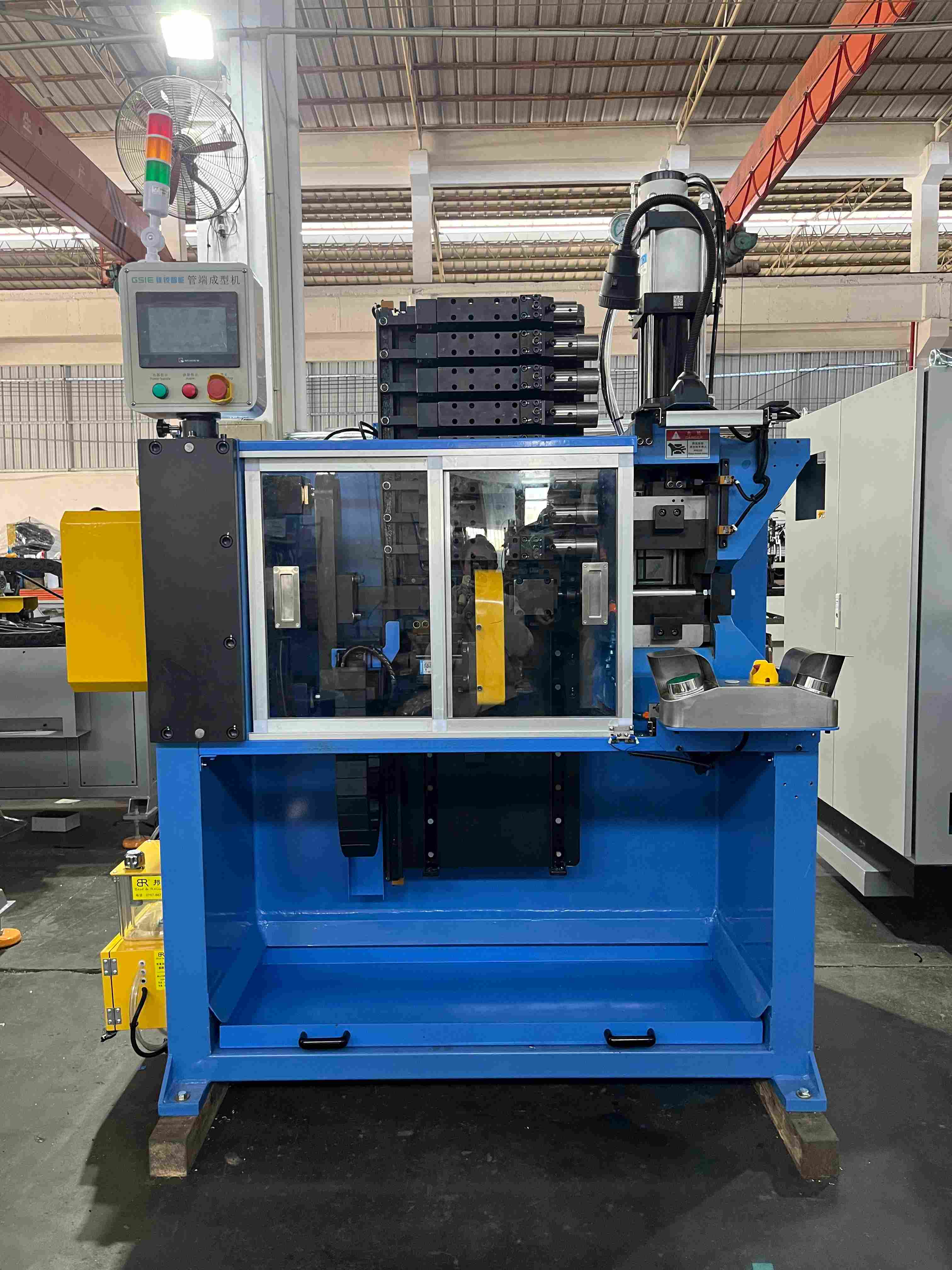
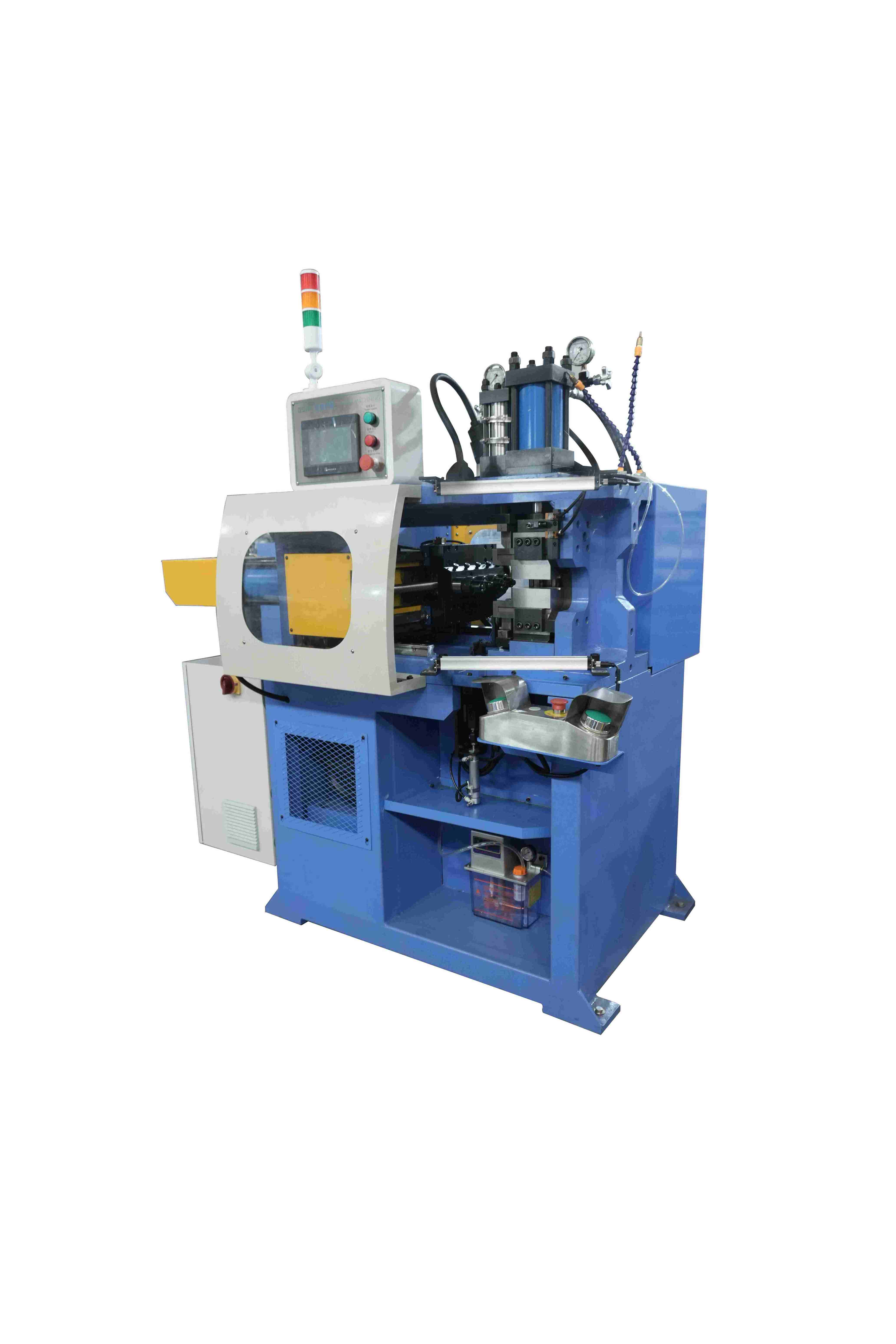
Hand tools are fine for repairs, but production flaring needs a machine that makes every flare the same. Most industrial flaring is done on a tube end forming machine, which can also chamfer, expand, reduce or bead the same tube. When comparing machines, check:
- Flare types and angles. The machine and tooling should cover the flares you need, such as 37°, 45°, double flares and flanges.
- Tube range and materials. Maximum OD and wall thickness for the copper, aluminum or steel tubes you run.
- Forming force. Enough force for steel and thick walls without overloading the frame.
- Number of stations. Multiple stations allow chamfering before flaring and progressive forming of double flares and complex ends in one clamping.
- Positioning accuracy. Servo-driven positioning keeps projection length, and therefore flare size, consistent.
- Automation. Automatic loading and unloading for high-volume lines.
GSIE machines for tube flaring
GSIE tube end forming machines handle flaring, expanding, reducing, and shaping of carbon steel, aluminum alloy, and copper tubes.
|
Model |
Key features |
|
Chamfering plus 4-station high-force extrusion for steel, copper and aluminum tubes up to Φ75 mm |
|
|
5 ram stations and double clamp dies for progressive forming, with automatic feeding and unloading |
|
|
8 servo-positioned forming stations with a dedicated chamfering unit, for tubes from Φ8 to Φ50 mm |
Conclusion
A good flare starts long before the punch touches the tube: a square cut, a clean, deburred edge, the right material and the correct projection length decide most of the result. Choosing the right flare type for the fitting and forming it on a machine that repeats every stroke turns flaring into a reliable, leak-free process. To find the right setup for your tubes, send your part drawing to the GSIE team.
FAQ
- What is the difference between a single flare and a double flare?
A single flare is the tube wall opened once into a cone. A double flare folds the wall back on itself before forming the cone, so it is twice as thick, stronger, and more resistant to cracking.
- Can I use a 45° flare with a 37° fitting?
No. The angles do not match, so the flare seats on a thin line instead of the full face and will leak or fail under pressure.
- Why do copper flares crack?
Most often because of burrs on the cut end; defects such as inner-surface scratches or inclusions in the tube; hard or work-hardened tube; or flaring too far in one stroke. Deburring, using annealed tube, and forming gradually prevent most cracks.
- Which materials can be flared?
Copper, aluminum, and carbon steel tubes are the most commonly flared. Softer, annealed tube flares more easily and with less risk of cracking.
- Can flaring be combined with other end forming operations?
Yes. Multi-station end forming machines can chamfer, flare, bead, or reduce the same tube in one cycle.